
Seal Support System
API PLAN 21
Menu
API PLAN 21
Production Description
-
API Plan 21 is a cooled version of API Plan 11.
In plan 21, the product from pump discharge
is directed through on orifice then to a heat
exchanger on cooler before being introduced
into the Seal chamber.
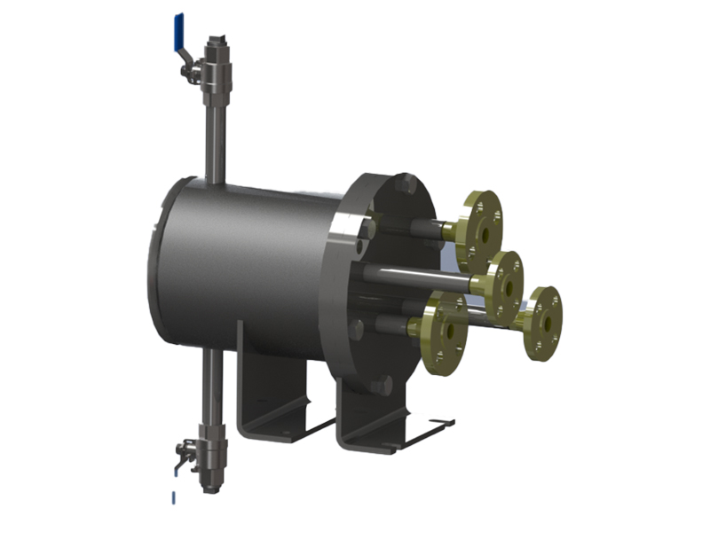
Heat Exchanger consists of single coiled or
double coiled cooling coils, outer shell, bottom
plate or bottom dish end, cover plate or top
plate, baffle plates, valves, flanges and pipe
fittings.
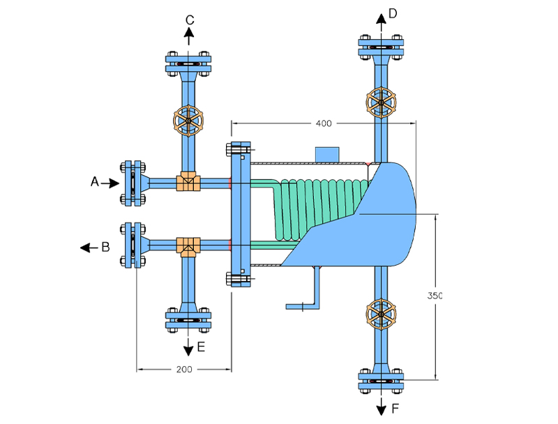
| Item | Description |
|---|---|
|
A |
Flush-Inlet |
|
B |
Flush-Outlet |
|
C |
Process Vent |
|
D |
Shell Went |
|
E |
Process Drain |
|
F |
Shell Drain |
Objective
- It is used to cool the hot process liquid from the discharge and supply the cooled liquid to the mechanical seal faces.
- With the help of orifice plate, cooled process liquid at the required pressure can be sent to the mechanical seal faces.
- It is commonly used plan if the margin between the vapor pressure & stuffing box pressure is less than 1 kg/cm2 at the pumping temperature
Advantages
- Provides cool discharge liquid to the mechanical seal faces.
- Maintains the product temperature margin (PTM) as required by API 682 Standard
- Removal of entrapped gasses through vent connection in the process inlet line.
- Ease of maintenance for coil & shell
Technical Features
- When used with a close clearance throat bush, the seal chamber pressure can be increased which can maintain the process fluid in liquid state
- MOC of cooling coil = SS316, SS316L, Incoloy 825, duplex SS MOC of Shell = Carbon Steel, SS316, SS316L Pipe and pipe – fittings = as per clients requirement.
- Baffle plate differentiate Cooling Water line and process line to provide counter – flow heat exchanger design
- Complete Heat Exchanger thermal design and mechanical design available on request
- Optional temperature gauge in the process return IS available to check the cooling efficiency of the heat exchanger.