Seal Support System
API PLAN 52
Menu
API PLAN 52
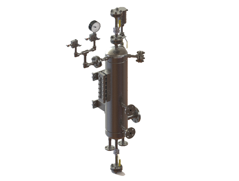
Product Description
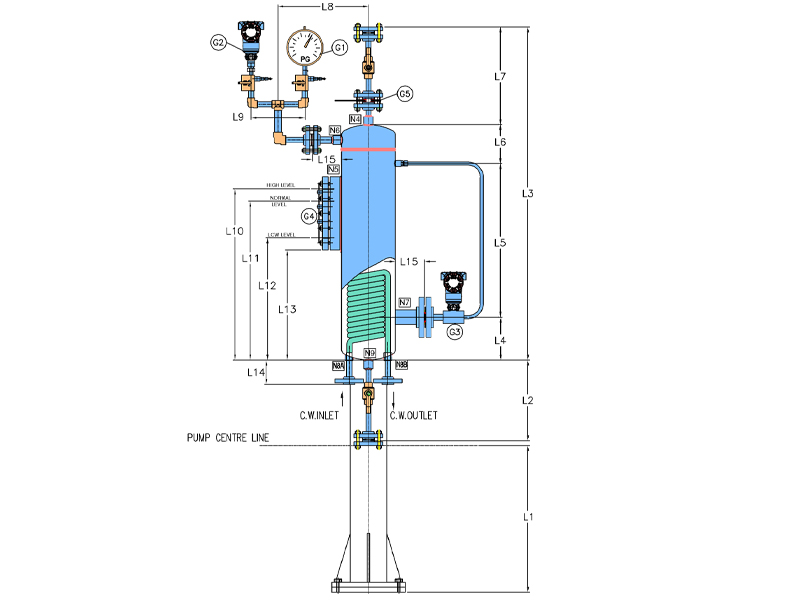
- API Plan 52 uses an external reservoir to provide buffer liquid for the outer Seals of arrangement 2 Seals. The buffer liquid shall be maintained at a pressure less than the seal chamber and less than 2.8 bar. It consists of a reservoir with capacity of 20 liters, cooling c oils, level gauge, level switch / level t ransmitter, pressure gauge, pressure switch / pressure transmitter, orifice plate, support pipe with pipe fittings.
| Item | Description |
|---|---|
|
G1 |
Pressure gauge |
|
G2 |
Temperature Trancemeter |
|
G3 |
Dp Tupelevel Trancemeter |
|
G4 |
Level gauge |
|
G5 |
Orifice Plate |
Objective
- It is used in services where the process fluid leakage to the atmosphere should be minimized and contained.
- It is used in applications where the process liquid may solidify on tends to be icy once the process liquid comes into atmosphere. The buffer fluid acts as a contained quench for the process liquid.
- It is also used in applications where additional heat removal from the inner Seal is required.
- Plan 52 works best with clean, non- polymerizing, pure products that have a higher vapor pressure than the flare pressure Leakage of higher vapor pressure liquid can escape either to flare line or to a suitable collection system.
- It is employed where inner seal leakage mixing with the buffer liquid is allowed
Advantages
- When the inner Seal fails, the outer seals take over there by giving buffer time for repair or maintenance activity
- No process liquid contamination
- Enhanced cooling of the inner & outer seals
- Best for hydrocarbons which are contained by safety back-up seal
- With flanged bottom connection the cooling coils can easily go for maintenance.
- An orderly shut down and repair of Seals is possible in case of failure of inner seals
- Monitoring of both inner seal leakage and outer seal leakage is possible through switches or transmitters linked to distributed control System (DCS)
Technical Features
- Level gauge can either be welded to the reservoir with borosilicate glass for viewing the level of buffer liquid
- Level switch / level transmitter can either be top mounted or housed in a separate housing
- Decrease in buffer liquid level indicates that outer seals has failed & increase in buffer liquid level indicates inner seal leakage
- Circulation is provided with the help of internal circulating services like pumping or pumping screw
- Designed in accordance with API 682 standard along with requirements meeting ASME Sec VIII Div.1
- Bottom flanged connections can be provided for ease of maintenance
- Available in various configurations based on flange type, class rating, external or inbuilt coolers
- Pressure switch / transmitter as additional monitoring for inner seal leakage
- Capacity at normal liquid level (NLL) = 20, Liters others available on client request