
Seal Support System
API PLAN 23
Menu
API PLAN 23
Product Description
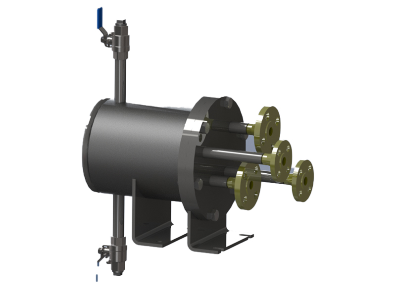
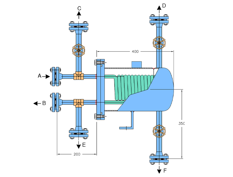
- API Plan 23 is recirculation of the process fluid from the Seal chamber, through a heat exchanger back into the seal chamber utilizing an internal circulating device like pumping screw, pumping ring or cutwater in the gland plate. It is a closed loop unlike plan 21 which is an open loop. Heat exchanger consists of single coiled or double coiled cooling coils, outer shell, bottom plate or bottom dish end, cover plate or top plate, baffle plate, valves, flanges & pipe fittings
| Item | Description |
|---|---|
|
A |
Flush-Inlet |
|
B |
Flush-Outlet |
|
C |
Process Vent |
|
D |
Shell Went |
|
E |
Process Drain |
|
F |
Shell Drain |
Objective
- API Plan 23 is used to cool the process liquid
- When used with a close clearance throat bush the process liquid is isolated hot from pumping process liquid so as to cool a smaller volume of liquid in the Seal chamber.
Advantages
- API Plan 23 being a closed loop, the duty the cooler is low as the cooler has to cool a little cooler liquid each cycle
- Close – clearance throat bush used in the Seal chamber increases the pressure of the fluid which helps to maintain it in liquid state.
- Internal circulating devices like pumping ring, pumping screw, provides the adequate flow rate and head provided the system curve resistance is kept to a minimum.
- Higher cooling efficiency as it continuously recirculates the seal chamber fluid.
- Reduction in cooler fouling both on the shell side & coil side
- No dilution of the process liquid is possible.
- Reduced operating temperature improves lubricity and reduce the possibility of vaporizations in the seal chamber
- Less scaling of salt deposits on shell side
- Provides cooled seal chamber for the standby pump due to thermo syphon effect
Technical Features
- Mechanical Seals employed for plan 23 shall use internal circulating devices like pumping ring, pumping ring screw or cutwater in the gland plate.
- MOC of cooling Coil = SS316, SS316L Incoloy 825, duplex SS MOC of Shell = Carbon Steel, SS316, SS316L Pipe & Pipe – fittings = as per clients requirement.
- Baffle plate differentiate Cooling water line and process line to provide counter – flow heat exchanger design.
- Complete thermal & mechanical design as per ASME Sec VIII Div 1, available on request
- Optional temperature gauge in the process return line available to measure the process outlet temperature.