
Seal Support System
API PLAN 76
Menu
API PLAN 76
Product Description
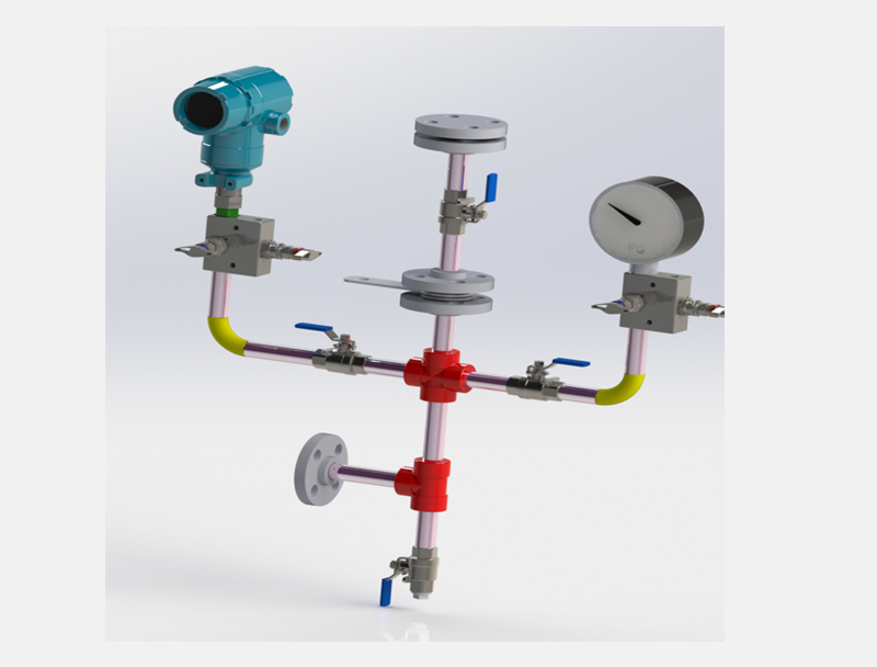
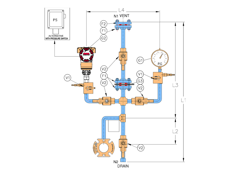
- API Plan 76 consists of simple piping including pressure gauge, pressure transmitter, orifice plate.
| P.No. | Description |
|---|---|
|
F1 |
Flange |
|
F2 |
Blind Flange |
|
V1 |
Two way manifold valve |
|
V2 |
Ball Vavle |
|
G1 |
Pressure gauge |
|
G2 |
Pressure Transmitter/Switch |
|
G3 |
Orifice-Plate |
|
N1 |
Vent |
|
N2 |
Drain |
Objective
- It is used to collect leakage for non- condensing liquid and route to flare line.
- This plan is used if the pumped fluid does not condense at ambient temperature
- They are used on arrangement 2 unpressurised dual seals, which also utilises a dry containment seal and where leakage from the inner seal is gas or vapour.
Advantages
- Least expensive
- Ease of maintenance
- Leakage is easily routed to vapor recovery system or flare system
- Simples piping
Technical Features
- Tubing or piping shall be minimum ½” and shall rise continuously upward from the CSV Connection.
- Leakage from the inner seal is restricted from escape by the containment seal and goes out of containment seal vent (CSV) Connection
- An orifice plate in the piping restricts flow such that or high leakage of the inner seal will cause a pressure increase and trigger the pressure transmitter to alarm at 0.7 bar (g)
- A drain connection on the piping may be u sed to inject nitrogen or other gas for the purpose of testing the containment seal.