
Seal Support System
API PLAN 72,74
Menu
API PLAN 72,74
Product Description
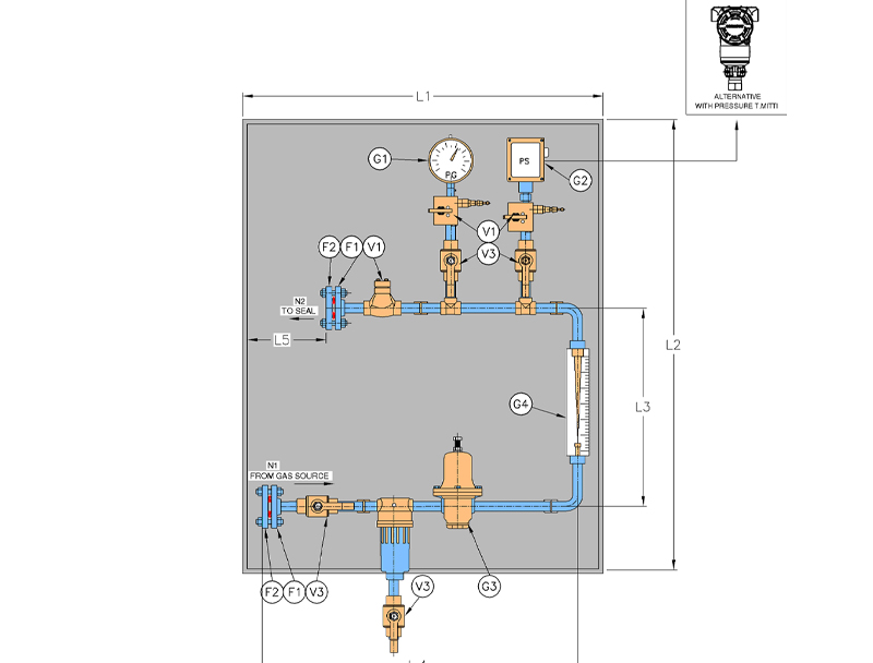
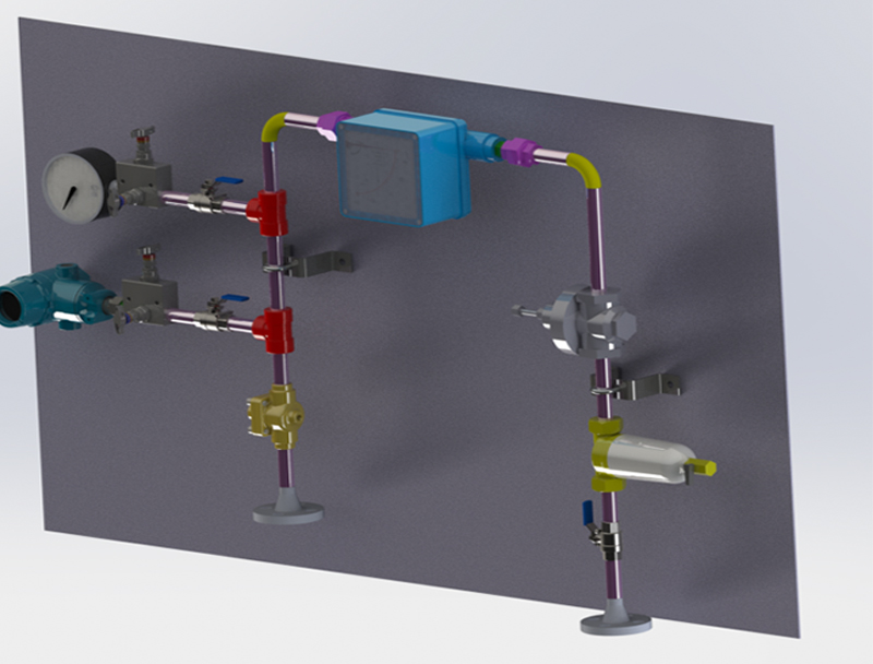
- API Plan 72/74 consists of filter, pressure control valve, pressure transmitter, flow-transmitter, check valve and pipe-fittings.
| P.No. | Description |
|---|---|
|
F1 |
Flange |
|
F2 |
Blind Flange |
|
V1 |
Two way manifold valve |
|
V2 |
Check Value |
|
V3 |
Ball Vavle |
|
G1 |
Pressure gauge |
|
G2 |
Pressure Transmitter/Switch |
|
G3 |
Pressure Reg |
|
G4 |
Flow Meter |
|
Mark |
Inlet (gas) |
|
N1 |
Vent |
|
N2 |
To Seal |
Objective
- API Plan 72 used on arrangement 2 unpressurised dual seals that uses a dry running containment Seal
- The buffer gas in API Plan 72 can be used to sweep the inner-seal leakage away from the outer seal to a collection system either to a reservoir or to flare line
- If leakage from inner seal is gas, the buffer gas will dilute the leakage and will reduce the leakage emission from the containment seal.
Advantages
- Life of containment Seal is enhanced
- Leakage is effectively routed to either liquid collect reservoir on flare line
Technical Features
- A coalescing filter removes any particle and liquid that might be present
- A forward pressure control valve which is set at plan 75 or plan 76 alarm point or at least 0.4 bar above normal flare pressure
- A pressure transmitter to ensure required pressure of the gas to reach the seal faces
- The flow transmitter will display the gas flow and will alarm on exceeding the flow
- API Plan 74 uses the same feature except that they are used on arrangement 3 seals. Barrier gas is maintained at 1.7 bar greater than the seal chamber pressure. It is equivalent to traditional plan 54 liquid barrier system.